"Modified SR Latch"

The Plan

My plan with this project was to design a circuit with one input which determines one output, such that when the input “button” is pressed, the output is inverted.

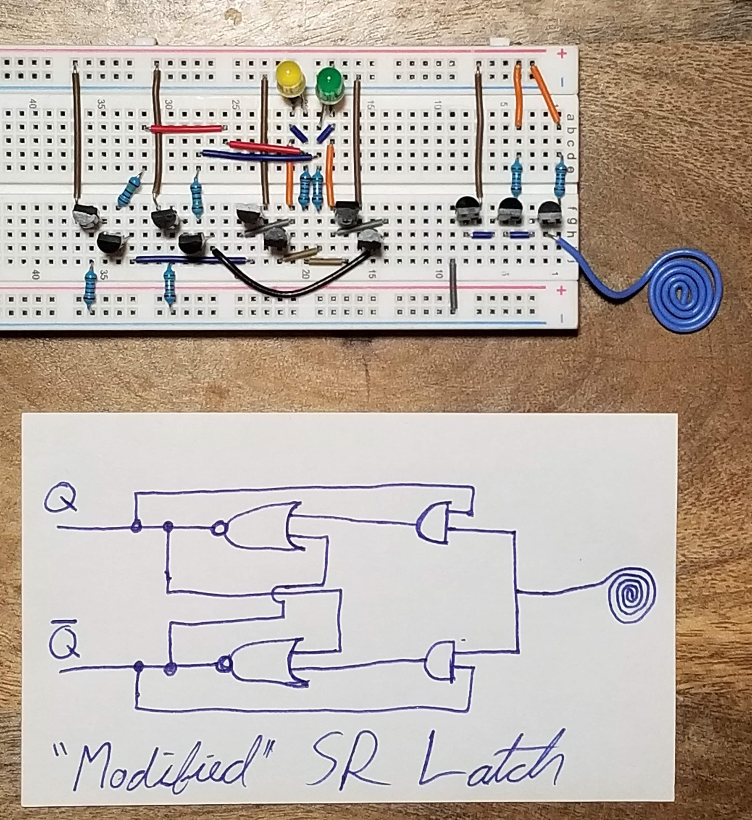
I began my design with the common NOR gate SR latch design as my base. I knew my circuit needed to combine both the set and reset input of the SR latch while also making sure neither are high at the same time.

The Process

The solution to this was simple, since, for example, if output Q is high, that output signifies that Q’s respective NOR gate is ready to be set low when either of it’s two inputs is set high again.

Therefore, the solution is to use AND gates to make sure a NOR gate in the SR-latch receives the now singular input, only when that NOR gate’s output is high.

In retrospect, this “modified” SR latch design is just a clockless T-flip-flop. At the time of this circuit’s making I was not familiar with the functions of a T-flip-flop, but understood latches, and I understood how to use the basic SR latch to achieve my goal of one input to control the output.

The Input

This part of the circuit is my experiment to make the input a bit more exciting than just a button. The coil is wired to the base of a Darlington configuration with three transistors so that when the coil is pressed with a finger, the very low voltage created is amplified by the configuration and inputted to the T-flip flop.